- call oalign.pro SLITNUM FILT1 FILT2 TARGNAME
- oalign.py OMSFILE MASKIMAGE ACQIMAGE
- oalign.py a267pmask.oms os20111029.0042b.fits os20111029.0043b.fits
no
Maskimage os20111029.0042b.fits title is: A267 P-Mask Mask Image
Alignment box coordinates file:  os20111029.0042b.box
Box coordinate files os20111029.0042b.box and/or os20111029.0042b.reg do not exist
z1=-28.61814 z2=29.67649

** Mark Alignment Star Boxes to use with a 'x'.
   and then press 'q' when finished.
   *** You must mark at least two (2) boxes ***

Log file _oalign.log open
and display this image:
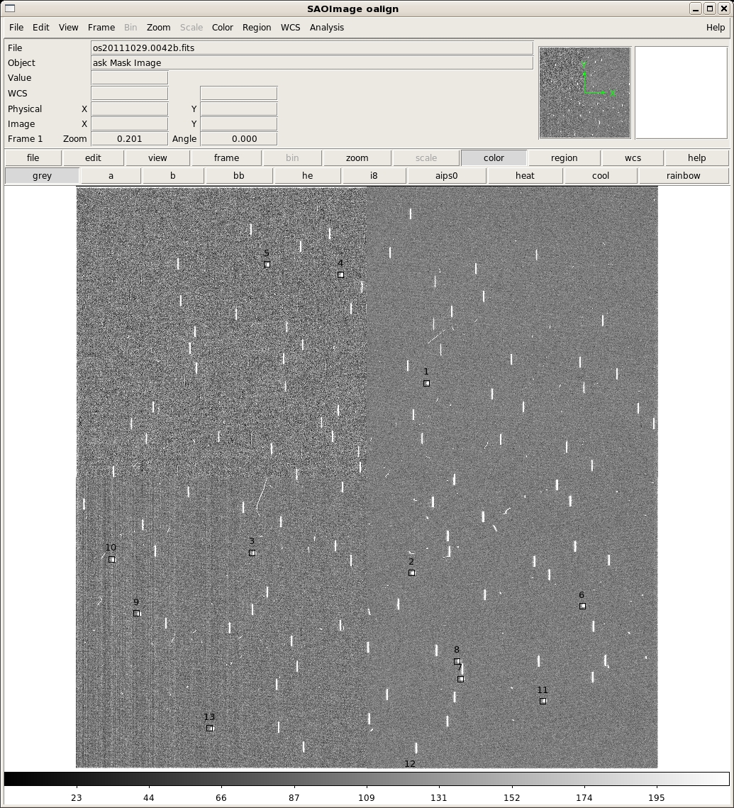
This image has a total of 13 alignment boxes (this is very excessive, and was just for testing -- four are recommended). The approximate locations of these alignment boxes were computed from the .oms file specified on the command line (a267pmask.oms in this example). All or any subset may be identified with the 'x' key. They may also be chosen in any order. If one picked the first three in this example and then typed 'q', the following will print to the screen:
2482.02 2711.24  1014.5
2382.36 1380.78  1144.5
1256.21 1510.34   1045.
0 Median at xc,yc is 1023.25
1 Median at xc,yc is 1103.75
2 Median at xc,yc is 1084.00
Min for all boxes is 1023.25
z1=-4.76159 z2=241.5081

** Mark the center of each alignment star with an 'a'
   and then press 'q' when finished.
   Stars must be selected in the *SAME ORDER* as the boxes.

Log file _oalign.log open
and now the acquisition image will be displayed in ds9:
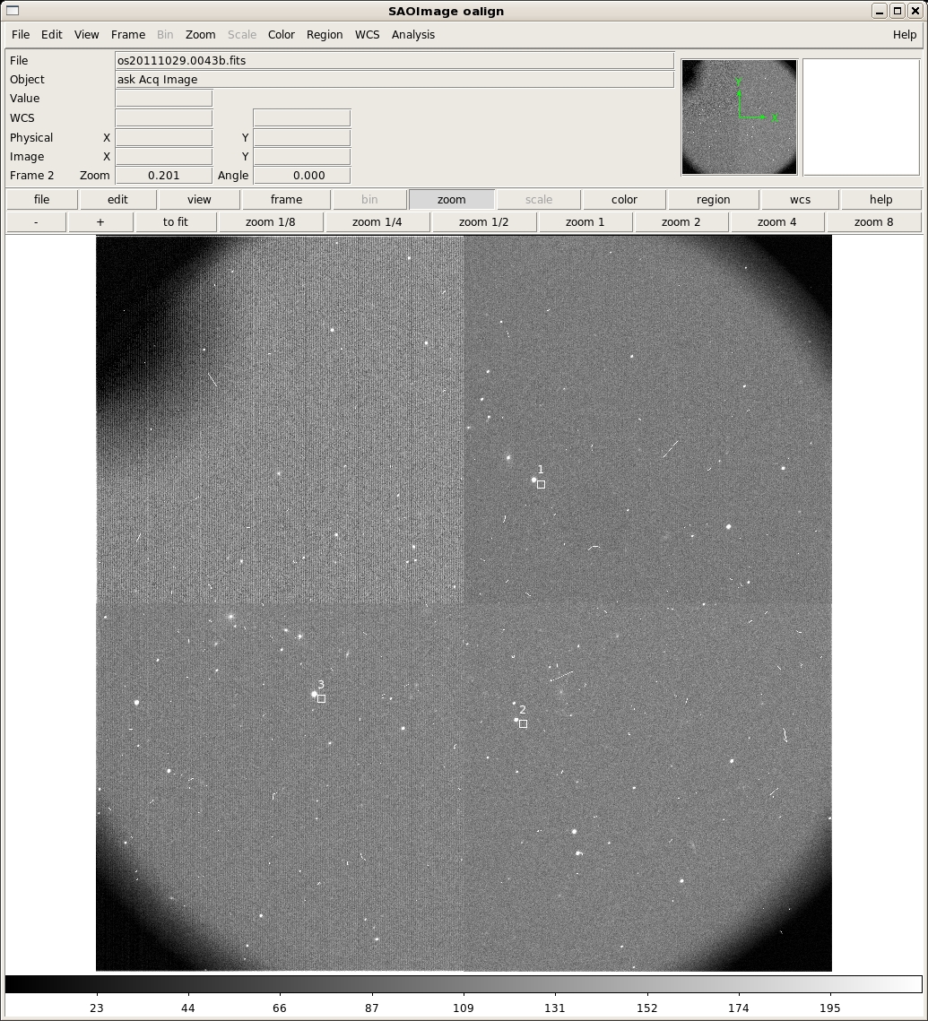
The first three rows of output in the terminal are the x,y pixel positions of the cursor when the 'x' key was typed and the counts in that pixel. After the 'q' key was pressed, the remaining lines print some debugging information. The ACQIMAGE will show the field, along with boxes at the centers only the alignment boxes identified in the previous step. Note that in the example only three boxes are shown, rather than all of them. They are also numbered in the order they were identified in the previous step, rather than the order they are listed in the OMS file. Identify the corresponding alignment stars in the same order with the 'a' key and then press 'q' when finished. oalign.py will then solve for and report the rotation and translation offsets. After you type 'q', oalign.py will solve for and report the rotation and translation offsets. In this example, the following is output to the screen after the 'a' key is pressed:
#   COL    LINE     COORDINATES
#     R    MAG    FLUX     SKY    PEAK    E   PA      ENCLOSED GAUSSIAN DIRECT
2437.50 2736.96 2437.50 2736.96
  19.28 -15.13 1.124E6    118.  21809. 0.19   44          6.83     6.36   6.43
2339.00 1403.59 2339.00 1403.59
  18.54 -14.19 473884.    122.   9226. 0.17   48          6.92     6.22   6.17
1215.46 1544.12 1215.46 1544.12
  19.30 -15.88 2.243E6    128.  40413. 0.21   45          7.12     6.57   6.43
Then, once the 'q' key is pressed the following output gives the solution:
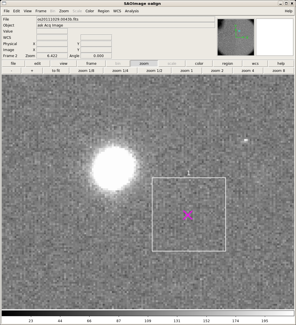
Geomap fit
0  2478.52  2712.74  2437.50  2736.96  2477.96  2712.32  -0.56  -0.42
1  2377.89  1379.30  2339.00  1403.59  2379.85  1378.92   1.96  -0.38
2  1257.67  1518.31  1215.46  1544.12  1256.27  1519.12  -1.40   0.81
# Geomap fit yields dx = 40.68 dy = -24.77 theta = 0.0169
Mean offset relative to solution is 1.44 pixels
ID BOX_X BOX_Y Star_X Star_Y New_Star_X New_Star_Y Delta_X Delta_Y Delta_S
0  2478.52  2712.74  2437.50  2736.96  2477.96  2712.32  -0.56  -0.42   0.70
1  2377.89  1379.30  2339.00  1403.59  2379.85  1378.92   1.96  -0.38   2.00
2  1257.67  1518.31  1215.46  1544.12  1256.27  1519.12  -1.40   0.81   1.61

Computed Mask Alignment Offset:
   dx:  11.104 arcsec
   dy:  -6.763 arcsec
  dPA: -0.0169 degrees

These are the guider offsets to apply:
   gdx: 86.2606 steps
   gdy: 141.6363 steps


And enter this rotation offset in the Rotator GUI:
   dPA: -0.0169 degrees


/home/tuatara/martini/programs/python/oalign.py done.
And the final image looks like:

The guider offsets are the 'gdx' and 'gdy' values. The rotation offset is the 'dPA' value. Before you apply them, inspect the output to determine if the solution is reasonable. First, look at the numbers in the columns labeled "Delta_X Delta_Y Delta_S." These are the dx, dy, and sqrt(dx**2+dy**2) residuals between the star and box positions in pixels after the solution is applied. Note that a pixel is 0.273", so more than two pixel offsets (particularly in x) is cause for concern. A second piece of useful information is to inspect the final image from oalign.py. There will now be a magnenta 'x' at the location where each alignment star will fall once the offset is applied. This should hopefully be at the center of the each box. Here is a zoom in to box one that demonstrates a good solution:
If one star has a substantially larger offset than the others, try to rerun oalign.py without that box/star (no need to take new observations).
Note that if this is a longslit acquisition, the syntax is:
- oalign.py -l SLITIMAGE ACQIMAGE