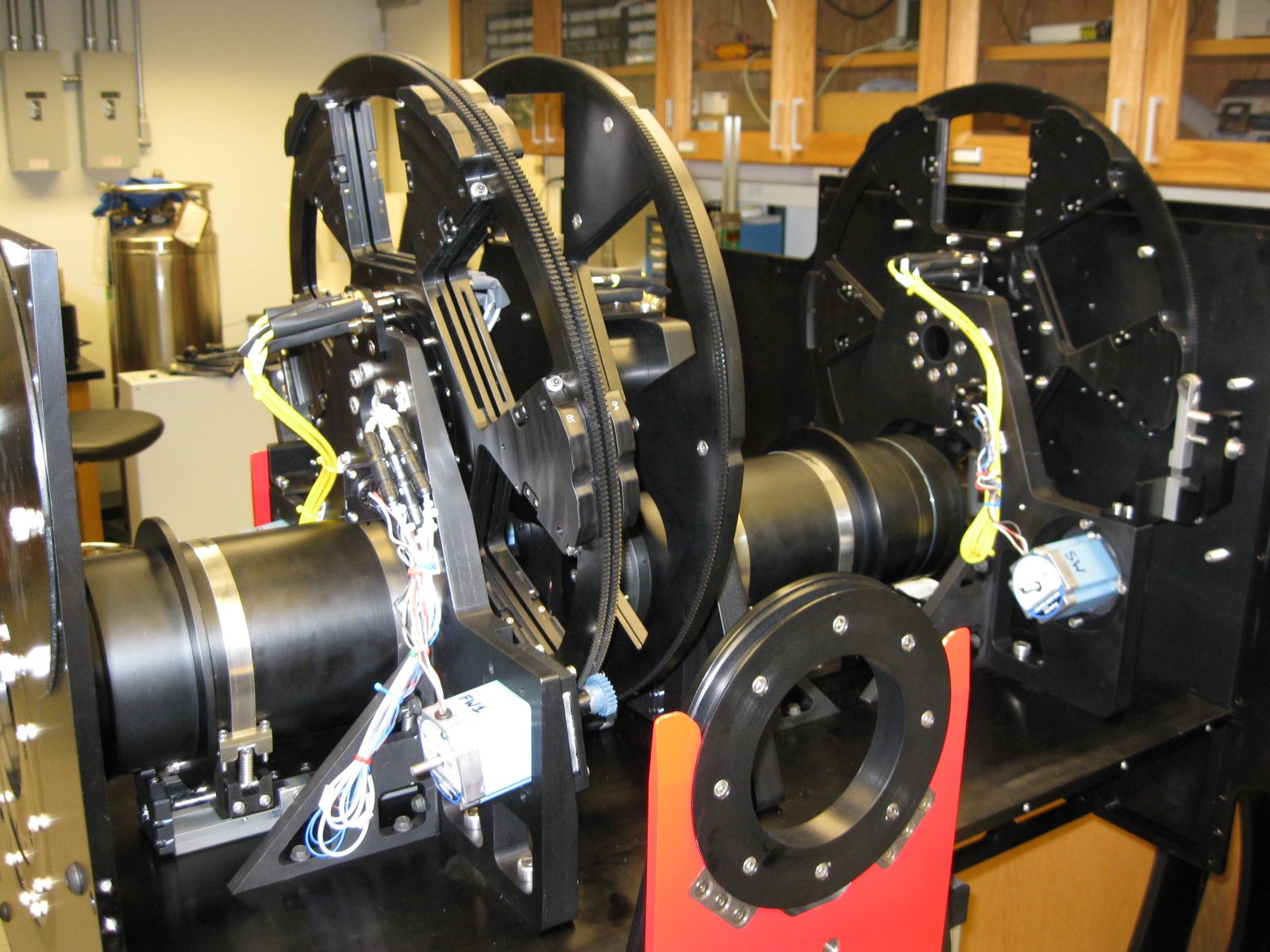
The complete OSMOS instrument, minus the side and top panels. From left to right are the camera lens barrel, the two filter wheels, the disperser wheel, the collimator lens barrel, and the slit wheel.
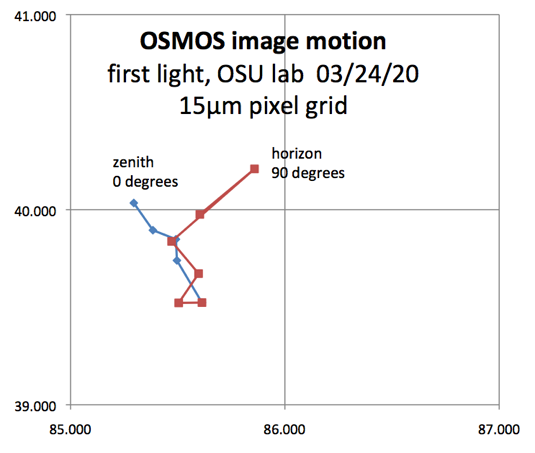
Measured image motion as OSMOS goes from zenith to horizon pointing in 10 degree increments. The rotation was perpendicular to the optical axis and in the plane of the optical bench (see cart pictures). The image motion has been projected onto the 15 micron pixels of the 4k CCD camera that OSMOS will use.
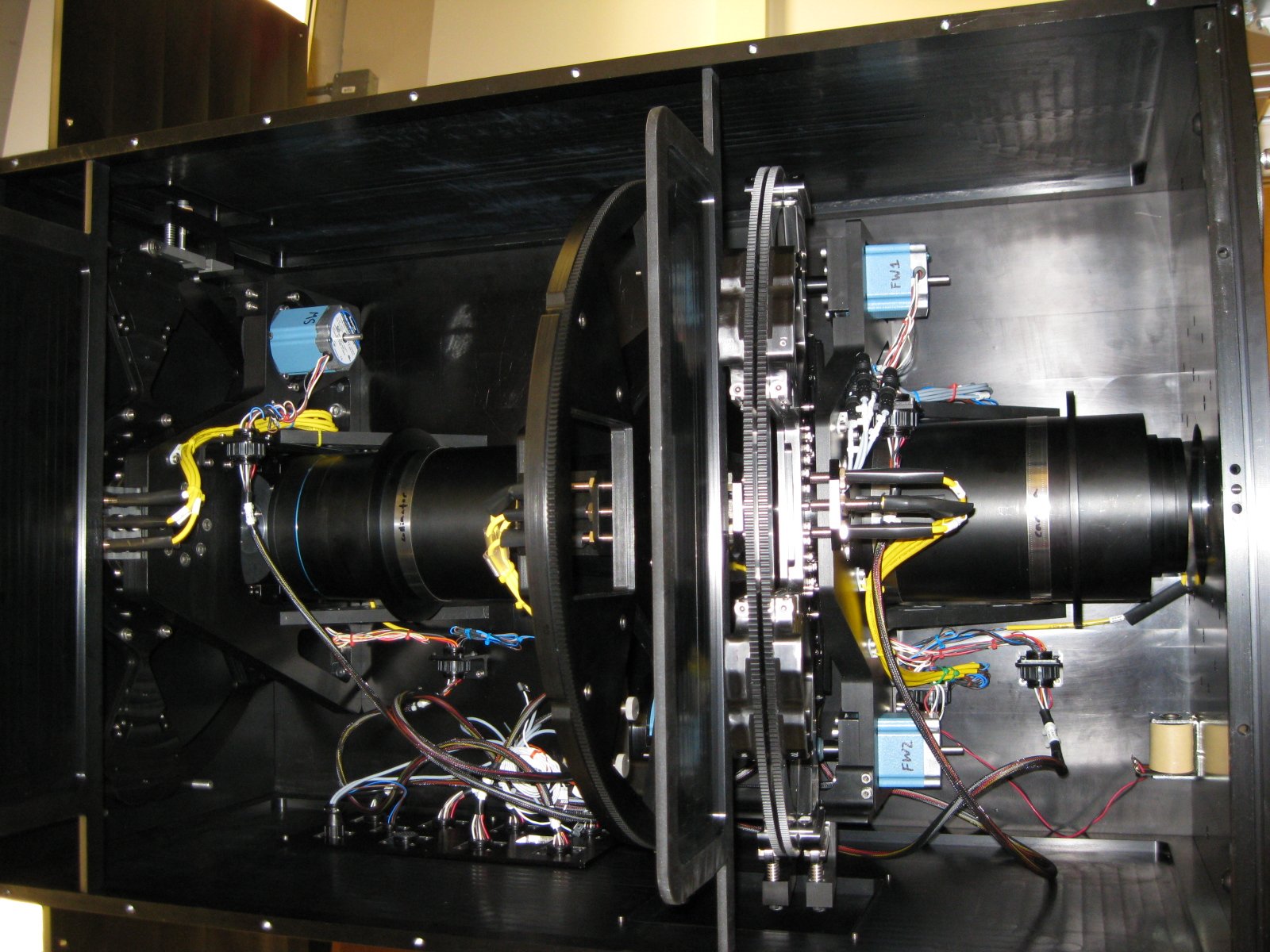
View of the OSMOS optical bench from above. The collimator is to the left and the camera is to the right.

Inside of the OSMOS Instrument Electronics Box. Some of the components visible include the MicroLYNX motor controllers, the WAGO I/O modules, and the Comtrol serial port server.
OSMOS pointing toward zenith on its cart.
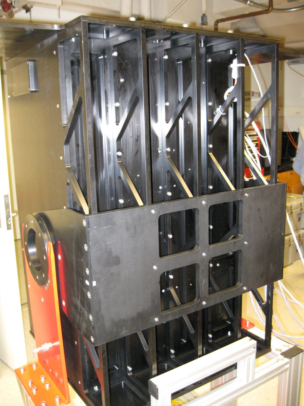
View of the rib support structure that provides stiffness to OSMOS' optical bench.