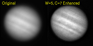
Notes on Contrast Enhancement using Digital Unsharp Masking Contents
Digital Unsharp Masking is a digital image processing technique that is used to increase the contrast in images where subtle fine details are set against a bright, diffuse background. It is a relative of a well-known photographic technique developed to enhance details lost in shadows without sacrificing bright objects in a scene. Australian astronomer David Malin has applied it to astrophotography with spectacular effect. The digital cousin, although operationally different in detail, has the same end in mind: enhancement of the contrast in small-scale features superimposed against a smooth, bright background.
The digital process works by subtracting from the original image an "unsharp mask" created by digitally blurring or "smoothing" a copy of the original image. This operation suppresses features which are smooth (i.e., which have structure on large scales) in favor of sharp features (those with structure on small scale), resulting in a net enhancement of the contrast of fine structure in the image.
Strictly speaking, this is really a "sharpening filter", not a photographic unsharp mask. The "unsharp mask" tools found in commercial image processing packages like Adobe Photoshop is primarily designed as a sharpening filter to be used on scanned photographs (either from print, negative, or slide sources). The scanner slightly blurs the image relative to the actual film resolution, and the "unsharp" tool seeks to restore some of the sharpness.
Photographic unsharp masking was originally developed by photographic artists. An original photograph of a scene is used to create a slightly out of focus ("blurred") inverted film mask. A contact print of the original is then made using this "unsharp mask" (carefully aligned with the original). The idea of the technique was to enhance the contrast of details hidden in shadows, without causing bright features to become saturated and lose detail. It was meant to work globally on the photograph, as a kind of overall "dodge and burn" technique (usually photographers would selectively enhance contrast in localized regions of a picture by masking off the rest of the image and only exposing the fainter portion they wished to enhance). The first application of photographic unsharp masking in astrophotography was at the Palomar observatory in the 1950s.
Digital unsharp-mask enhancement requires the following steps:
Each of these steps are described below, along with a worked example.
Prepare the Image
Digital image enhancement of any kind is exquisitely sensitive to artifacts in the image: hot or dead pixels (either individual or in clumps), streaks, blocked columns, and cosmic ray streaks. The best results are obtained if your images are carefully cleaned of such artifacts before proceeding. For example, interactive median filtering (e.g., the imedit task in IRAF) is often used.
Create a Smoothed Version of the Original
The first step after you have a clean image is to create a smoothed copy of the original image. The typical smoothing kernel used is a 2-D "boxcar kernel". It is possible to use other kernels, like Gaussian or Hanning kernels, but boxcar is the easiest to do computationally, especially in cases where the seeing is oversampled by small pixels (this is the case with images acquired for this lab).
A boxcar kernel smoothes the image by replacing each pixel in the original image by the arithmetic mean of all neighboring pixels falling within a square of width W pixels centered on the pixel of interest. To ensure that the smoothing kernel is symmetric, W should be an odd number.
In the smoothed image, sharp features (those whose characteristic scale is of order W pixels) are blurred out, while smooth features (those with structures on scales greater than W pixels across) will be relatively unaffected.
This smoothed image is now the "unsharp mask" image, SW.
Intensity Scaling & Subtraction
Once an smoothed version of the original image has been created, it needs to be scaled in intensity and subtracted from the original image. The scaling is parameterized by a "contrast factor", C, which sets the relative contributions of the original image and smoothed image to the final enhanced image. For example, a contrast factor of C=2 would create an enhanced image in which the mask subtracted contained 50% (1/C) of the mean background level. The larger C, the higher the contrast. If C is too high, however, the result will be to over-enhance, leading to undesirable artifacts.
The final unsharp-mask enhanced image, EW,C, is formed from the difference of the original image (I) and the unsharp mask (SW), scaled by C, such that:
EW,C = C*I - (C-1)*SWwhere:
A 10msec CCD image of the Moon (near first-quarter) was taken with a 12-inch telescope under conditions of 2-arcsecond seeing (integrated seeing was worse, ~4 arcsec, but we took many images and selected the ones with the sharpest instantaneous seeing during the brief 10msec integrations). The pixel size on the images is 0.38 arcsec/pixel, or roughly 5 pixels per FWHM. The goal is to enhance the contrast of the images to see the lunar features more clearly against the bright lunar background.
Figure 1 shows the results of applying our algorithm with a boxcar smoothing kernel with W=7 and a contrast factor of C=7. These were chosen arbitrarily for the purposes of illustration, but W was chosen to be a little larger than the seeing width (~5 pixels), for reasons that will become clear below.
The original image is shown on the left, followed by a W=7 smoothed version (center), and the final C=7 contrast enhanced image (right). Each image is displayed with the same min/max intensity levels [click on any of these images to see the full-resolution version (these are GIFs that range in size from 58-130KB)].
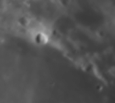
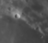
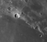
Note that while the effect of smoothing this relatively low-contrast image by a W=7 boxcar kernel is somewhat subtle (center), the contrast-scaled difference (right) is fairly dramatic.
Figures 2 and 3 below illustrate the effects of making different choices for the smoothing width and contrast factor. In Figure 2, we hold the contrast factor fixed at C=7, and choose different smoothing widths of W={3,5,7}. Note that significant contrast enhancement does not begin to become apparent to the eye until the smoothing width is of order the seeing width (here ~5 pixels).
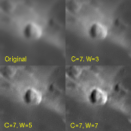
Figure 3 shows the effect of holding the smoothing width fixed at W=7, and choosing contrast factors of C={3,5,7}. As C increases, a greater fraction of the smoothed mask is subtracted, resulting in higher contrasts (bright peaks get brighter, dark valleys get darker).
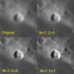
In both cases, clicking on the images will download a higher-resolution version (full-size GIFs are ~90KB each).
While the image looks sharper, closer inspection of the images also reveals that the enhanced image is also substantially noisier. This is best seen in Figure 4, which shows the greater amount of pixel-to-pixel variation in a 64x64 pixel portion of our lunar image, zoomed into the smooth maria south of the larger craters in Figures 1-3.
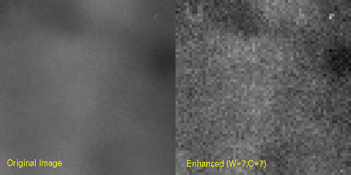
The rms pixel deviations (sigma) in the original image are +/-53.0 ADU versus +/-80.5 ADU in the enhanced image. The mean intensity levels are 1364 and 1363 ADU, respectively, showing that the processing preserves the mean flux in the images, if redistributing in certain regions to enhance contrast.
The effect of increasing C is to increase the amount of noise, as shown in Figure 5, where the mean and rms (sigma) are plotted for this region for contrast factors of C=[2-11] (inclusive) for a W=7 smoothing filter. Notice that the mean does not change while the rms increases monotonically with increasing contrast factor C.
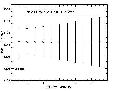
Fig 5: Increase in rms pixel noise in the region shown in Figure 4, for W=7, C=2-11 enhanced images. The original mean and rms is shown as the filled point.
Note that while the total flux in the image is conserved in this procedure, the S/N is decreased overall, and the photometry of detailed regions is compromised. This illustrates that although unsharp-masking can be useful for helping to identify fine structure in low-contrast images, it cannot be used for images for which detailed photometric analysis is required.
A way to understand how digital unsharp masking works is to first consider the simple derivative image. Make a copy of an image, shift it by one pixel along both axes relative to the original, then divide the original by the "shift-by-one" image. Real features will show up as shadowy lumps; bright/dark artifacts along the 45-degree gradient of your 2-axis shift. In effect, you have computed the derivative of the intensity along the 45-degree vector. You can also form an image shifting an any other direction, resulting in an approximation of the derivative of the intensity along that direction. If you shift by a greater amount, the effect will be enhanced, until you shift so far away that neighboring structures are just beating against each other, and all you get is hash (although the smooth structures will start to show the effect, more subtly, as you start to shift the two images by an amount comparable to the characteristic sizes of the smoother structures). This is illustrated in Figure 6, where we show the region around one of the craters, followed by the dx=1, dy=1, and dx=dy=1 derivative images.
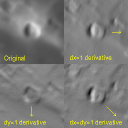
Fig 6: Derivative images for formed by dividing the original image (top left) by itself after shifting left by 1 pixel (top right), down by 1 pixel (bottom left), and by 1 pixel left and down (bottom right). The intensities in the derivative images show +/-20% around 1.
Building on this analogy, unsharp-mask contrast enhancement is playing with the first derivative of the image. By using a boxcar kernel, the smoothed unsharp mask image (SW) is an average of shifting the original image in all directions by the half-width of the filter (instead of just in a single direction as in the example above). When the difference is formed, the sum of all the derivatives serves to "move intensity" into locally sharp peaks (up the local gradients) and out of locally sharp valleys. Smooth features, which vary on longer scales than the width of the averaging filter, are relatively unaffected. The contrast factor C changes the weighting: the larger the factor the more you weight the local gradients. If you form the unsharp mask image by using some other smoothing kernel (e.g., a Gaussian or pyramid kernel), all you are doing is changing the weights in a complex way with direction away from the center. I find that using other smoothing kernels less intuitive than the boxcar filter, and so have highlighted it here.
A better name for this technique might be "Intensity Gradient Enhancement", which is closer to the operational description. The analogy with photographic unsharp masking (a different process), however much it irks professional photographers, has apparently stuck, so "Digital Unsharp Masking" it is.
It is often said that unsharp masking improves the seeing of images by enhancing angular resolution. This is false. The seeing (original degree of image blurring due to atmospheric turbulence) is the same before and after unsharp mask enhancement, only now the contrast of faint features is greater. While this is analogous in effect to what happens in conditions of better seeing, insofar as sharp features are less blurred and so have greater contrast against smooth backgrounds relatively unaffected by atmospheric seeing, there is no increase in net angular resolution after unsharp-mask enhancement. This means that two point-sources that are blurred together by seeing will not become more distinct from each other after unsharp masking (as would occur if the angular resolution could be improved). Techniques for improving angular resolution are outside the scope of this discussion.
If all you have is a hammer, everything looks like a nail...
If you read the CCD magazines, and the brochures and websites for image processing packages, you come away with the distinct impression that some people use their image processing software on their images in the same way that one uses a food processor on food. The result is the same: sometimes you get good food, other times you get hash. Injudicious use of any image enhancement technique, however cool, will give you hash.
Contrast enhancement tricks like unsharp masking have their particular role to play, but they should not be applied to all images without thought. The examples here were specifically chosen to be the most illustrative of the generally most appropriate cases: high signal-to-noise but otherwise low-contrast scenes with subtle fine structure. The effect of poor seeing is to wash out contrast in objects for which contrast is already a problem. The Moon, resolved planetary disks, some bright diffuse nebulae, even a galaxy or two can benefit from a technique like unsharp masking. Most of other types of objects, however, like images filled with many stellar images, do not. A common artifact of the unsharp mask enhancement is to leave "moats", regions of negative pixels, surrounding what used to be more or less clean stellar images. The reason is simple, if you try to jack the contrast on something that is already high contrast, you can get garbage out (viz. food processing). You enhance the contrast in real features, but you also enhance noise at the same time; the technique does not distinguish between the two.
A common misuse of unsharp masking is to try to bring faint stars out of the sky background. Bad idea. While unsharp masking is globally flux conserving, it does not conserve flux locally, roughly on the scale of a few times the smoothing width. You try to enhance faint features like stars out of a background and you might just elevate local noise to the status of star-hood. Bad idea. If you want to see faint stars, get better signal-to-noise ratio data and integrate longer, building up better sky and faint star statistics.
Finally, the best rule of thumb is, if you can't already see a feature a some level in the raw image, unsharp masking (or any other contrast enhancement technique) won't show it to you. If structure is there, enhancing the contrast with an unsharp mask might help you locate it, but you won't be able to do photometry on it in the enhanced image. You can, however, do it in the original, now that you know where it is, but you are back to where you were with regards to contrast against the background. If you want a better measurement, get better signal-to-noise data.
There is no substitute for good seeing and adequate signal-to-noise.
Persons other than Astro350 students (who already have access to the data files) who would like to experiment with these data are welcome to the original data and procedure scripts used.
The unprocessed image is in the file:
Users of xvista can also download a copy of the unsharp.pro procedure script that did all of the processing shown above (7Kb ASCII text). IRAF users can easily figure out how to write the analogous cl script from this procedure (it is quite simple).