
|
The Ohio State University
College of Mathematical & Physical Sciences
Department of Astronomy
|

OSMOS User's Manual
The new R4K detector system was commissioned in September 2011. Click
here for further details and pictures.
The multi-object capability was commissioned in May 2011. Click
here for further details and
pictures.
Contents
- Summary
- Quick Reference
- Performance
- Overheads
- Detectors
- Shutter Timing
- Multi-Object Spectroscopy
- Startup
- Collimator and Camera Focus
- User Interface and Prospero
- Guiding
- Longslit Acquisition
- Multi-Object Acquisition
- Instrument Configuration
- Flat Fields
- Wavelength Calibration
- Data Analysis
- Technical Information
- Troubleshooting
- Team
- Sponsors
OSMOS (Ohio State Multi-Object Spectrograph) is a wide field imager
and multi-object spectrograph that was commissioned at the 2.4m
Hiltner telescope at the MDM Observatory in April
2010. OSMOS employs an all-refractive, zero-deviation design that
projects a plate scale of 0.3-arcsec/pixel and a 20-arcmin diameter
FOV onto the MDM4K or R4K detector systems. There is a 6-position slit
wheel, a 6-position disperser wheel, and two 6-position filter
wheels. The slit wheel may contain either long slits or customized
masks that are laser cut into spherical, NiColoy masks that match the
curvature of the 2.4m focal surface. Up to 50 to 100 slitlets should
be feasible per mask. The current complement of dispersing elements
includes a very low resolution triple prism and a high-efficiency,
low-resolution VPH grism (R=1600, peak at 450nm). Anyone interested in
supplying additional dispersers is encouraged to contact Paul Martini.
Click here for construction photos.
More information is available via these
detailed instrument characteristics and these two papers:
- Mechanisms and Instrument Electronics for the Ohio State
Multi-Object Spectrograph by Stoll et al. 2010, SPIE, 7735, 154
- The Ohio State Multi-Object Spectrograph by Martini et al. 2011, PASP, 123, 187
Please consider citing these papers in any publications that employ
new data from OSMOS.
- Imaging
- Plate scale: 0.273 arcseconds per pixel
- Unvignetted Field of View: 20-arcminute diameter circle,
detector subtends a 18.5x18.5-arcminute square
- Filters: All
MDM Filters (4-inch filter cell) + New
izY DES filters
- Performance: See the magnitude zeropoints in the Performance section below
- Image Quality: FWHM in UBVRI as a
function of field angle for OSMOS only (atmosphere not included)
- Finding charts: An easy way to generate them on the fly is with
ds9 (Analysis -> Image Servers -> SAO-DSS)
- Spectroscopy
- Long slits: 0.9, 1.2, 1.4, 3, and 10 arcsecond wide slits are
available (they are nearly 20' long). The 0.9" and 1.2" (both center
and inner) are loaded by default. Please specify other choices on your
setup form.
- Triple prism: R=100-400 (highest resolution in the UV), 360-1000nm
[Resolution vs. Wavelength for a 3-pixel
slit]
- VPH grism: R=1600 (0.7 A/pix), ranges of 310-590nm (peak at 500nm)
and 390-680nm (peak at 640nm). See the Wavelength
Calibration section for more information. [Predicted Efficiency (for a centered
longslit)]
- Acquisition: There is no slit viewer. See the Longslit Acquisition or Multi-Object Acquisition sections for more
details on how to acquire objects for spectroscopy.
- Multi-Slit Masks: Custom, laser-cut slits in electroformed
spherical shells of NiColoy coated with Copper Oxide (CuO)
black. Please see the section on Multi-Object
Spectroscopy for information on mask design.
- Orientation: Please specify either E-W or N-S orientation for
slits (with the rotator at 0 degrees) in your setup form. Note that
the wavelength solution zeropoint varies more with the N-S orientation
due to instrument flexure.
Here is an OSMOS logsheet.
There are numerous useful Prospero scripts in the Scripts/ directory on
the 2.4m observer's workstation (mdm24ws1). Observers are encouraged to look through
these scripts. A brief guide to the most useful scripts may be written in the future.
Photometry
Photometric magnitude zeropoints for OSMOS were measured in April 2010 with the MDM4K and in September 2011 with the R4K.
These magnitude zeropoints correspond to 1 e- per second.
| Vega magnitudes, MDM4K |
| U | B | V | R | I |
| ... | 24.5 | 25.0 | 25.3 | 24.8 |
| AB magnitudes, R4K |
| g | r | i | z | Y |
| ... | ... | 25.5 | 25.0 | 23.7 |
Paul Martini's page on Useful Astronomical Data has information about Flux Zeropoints.
Spectroscopy
Basic information about wavelength coverage and resolution is available in
the Quick Reference section. More details on
performance will be posted shortly.
The OSMOS slit, disperser, and filter wheels require up to 3 seconds to
change configuration and the instrument can consequently be reconfigured
quite rapidly. Detector readout varies from tens of seconds to two minutes,
depending on binning and whether the full chip is read out. Long slit
acquisition takes approximately five minutes, although may require more time
if there are problems with the telescope offsets. Here is a table that
summarizes these overheads:
- slit/disperser/filter wheel move: 3 seconds (max)
- full detector readout binned 1x1: 134 seconds
- full detector readout binned 4x4: 16 seconds
- 1k x 1k detector readout binned 1x1: 15 seconds
- Long slit acquisition: 5 minutes (variable)
The next subsection contains more information about the detectors.
OSMOS may be used with either the
MDM4K or the
R4K detector. Both are 4k squared devices with 15um
pixels. The MDM4K has better sensitivity
in the blue and the R4K has better sensitivity in the red. Here is a
QE comparison figure that is based on data from
the manufacturers. The R4K also exhibits substantially less fringing, but
does have a higher rate of radiation events (a.k.a. cosmic rays).
Region of Interest
One may reconfigure either detector to read out a specific 'Region of
Interest' (ROI), rather than the full detector. This mode has the
advanges of faster readout and smaller image files and may be
particularly valuable for judging when to start twilight flats, focus
sequences, and spectroscopic observations. Configuration files for 1k
square, 2k square, 1x2k, and 1x4k regions centered on the detector are
presently available. To implement an ROI for the MDM4K in Prospero
type:
- pr> call roi1k
- pr> call roi2k
- pr> call roi2x1k
- pr> call roi4x1k
and type
- pr> call roi4k
to return to full frame readout. For the R4K detector the commands are
instead:
- pr> call rroi1k
- pr> call rroi4k
etc.
Note that the 2x1k ROI is well-suited to single-object spectroscopy
with the triple prism and the 4x1k ROI is well-suited to single-object
spectroscopy with the VPH grism. (The old 'init' versions of these ROI
scripts were replaced with the present set of 'roi' scripts in October
2011.)
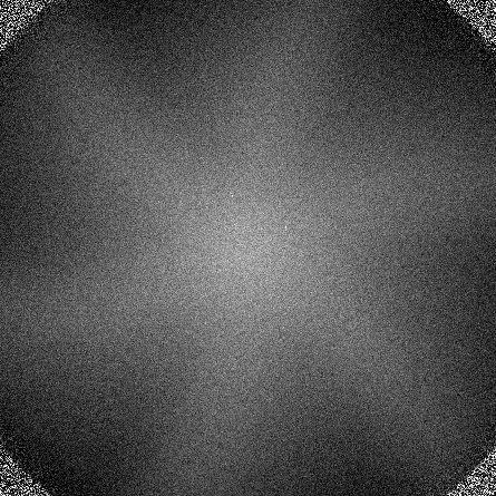
OSMOS uses a Prontor/E100 shutter. This is a leaf shutter that may introduce
timing errors in short exposures. To attain better than 1 percent
measurement precision, one should employ exposures longer than 10 seconds
(including for twilight flats). The figure below demonstrates the
shutter timing error for a 1s exposure. In this image the peak at the center
of the field is approximately 5 percent higher than at the edges.

Mask Preparation
Observers interested in multi-object masks presently should
contact Paul Martini at least two months before their run.
OSMOS masks may be designed with a software package called
OSMOS Mask Simulatior (OMS)
OMS is a slightly modified version of MMS,
which is the mask design software for MODS (MMS is in turn a slightly modified
version of LMS,
which is the mask design software for LUCI). In addition to the OMS web page,
the web pages for MMS and especially LMS contain additional documentation.
Mask alignment is performed with alignment stars. These stars will have
square apertures in the mask at their locations relative to the
slits. While in principle only two are necessary to solve for the
rotation and translation offsets required for mask alignment, at least
four are recommended to guarantee a good solution. To speed the mask alignment
process, these stars should be in the central 4x1k region of the detector so
that this ROI may be used to align the mask. These stars should also be
well distributed across the field to maximize the lever arm for the
rotation offset calculation.
The outputs of OMS include a file in gerber format (.gbr extension) that
contains instructions to the laser cutting machine on how to cut the mask
and mask description file (.oms extension) that describes the mapping
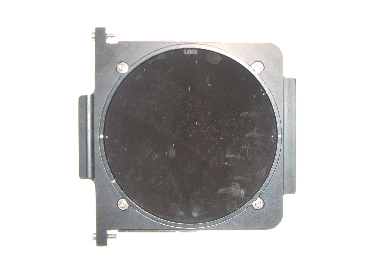
between targets and the slit mask. Note that it may take up to a month to
arrange for the masks to be cut. Observers will consequently
need to send their final mask designs to Paul Martini at least a month in
advance of their run to guarantee that the masks will be ready. An
image of an OSMOS mask in a cell is shown
here
The cost per mask is still TBD, but will likely be $150 to $200. This
cost covers the electroformed spherical shell and the labor for the
laser machine operation.
Multi-Object Observations
Multi-object observations are similar to longslit observations, with the
exception that the rotator angle must also be set very precisely (to within
0.01 degrees). This can be achieved with custom mask alignment software
available at the telescope and is described in the section on
Multi-Object Acquisition.
Guidelines for Calibration
The present MIS calibration system does not uniformly illuminate the
entire OSMOS FOV. A reasonable solution is to simply take very long
exposures during the afternoon until sufficient signal is obtained
in all of the slits for both arc lamps and spectroscopic flats.
Twilight spectroscopic flats could be used to remove the non-uniformity
of the illumination by the MIS flat lamps. See also the section on
Flat Fields for more information.
The zeropoint of the wavelength solution will likely drift between the
afternoon calibations and the nighttime observations due to instrument
flexure. Sky lines could be used to compute this zeropoint offset.
See also the section on Wavelength Calibration for
further information on specific dispersers.
OSMOS will typically be ready for operation when observers arrive for their
first night. The MDM staff will perform the following tasks
before a run, but they will be necessary for observers to follow in the event
of a power failure or lightning shutdown:
- Turn on the IC (Computer Room) and type 'O' for OSMOS and choose the appropriate detector.
- Turn on the Instrument Electronics Box
- Turn on the Head Electronics Box
The next step is to launch various control clients and the User Interface
on the 2.4m Observing Workstation. From the
"Applications"..."Data Acquisition" menu
at the upper left-hand corner of the desktop's menu bar, select the
following options in the order they are listed:
- ISIS
- MDM TCS Agent
- Caliban
- OSMOS IE Agent
- Prospero
Then type startup in Prospero to load the current instrument
configuration.
The last step is to initialize the OSMOS mechanisms, including
setting the collimator and camera lens barrels to their nominal
15°C positions. To do this, type:
pr> call ossetup
Details of how to set the nominal focus of the camera and collimator
lenses for different seasons is described in the
focus section of this manual.
Finally, make sure that the OSMOS instrument hatch is open.
OSMOS has its own instrument hatch that is separate from the MIS hatch.
The lever to open and close this hatch is on the opposite side of the
instrument from the access doors for the slit and filter wheels.
There is a separate web page with Detailed Startup and
Usage Information.
OSMOS has two internal focus stages, one for the collimator and one for the
camera. If the IEB power is cycled, these stages need to be reset with the
following commands:
- pr> colfoc reset 2300
- pr> camfoc reset NNNN
where NNNN is the temperature-dependent focus value for the camera:
- T=15°C: 5800
- T=25°C: 5300
These commands take approximately 5 to 10 seconds to execute each.
OSMOS is operated with the Prospero User
Interface written by Rick
Pogge. Please see his extensive online documentation for general
information about how to use this software. Below is a brief synopsis
of the most commonly used commands.
Basic Commands
The instrument configuration is controlled with six basic commands:
- pr> slit N
- pr> disp N
- pr> filter1 N
- pr> filter2 N
- pr> colfoc FFFF
- pr> camfoc GGGG
The slit, disperser, and filters take an integer argument [1-6] that
corresponds to the desired aperture position. Executing the command with
no arguments will return the current position of the wheel. The collimator and
camera focus stages are controlled with the colfoc and camfoc
commands, respectively. An integer argument to these commands (i.e. the
FFFF or GGGG variables above) moves the appropriate stage to that absolute
position in microns.
Data Acquisition
| pr> go | take an exposure |
| pr> exp T | set the exposure time to T seconds |
| pr> object name | set the object name to name |
| pr> filename name | set the filename to name |
| pr> print wheel | print the current population of wheel [slit, disp, or filter] |
| pr> call script | run the Prospero script named script.pro |
| pr> snap | take an image but do not save it to disk |
| pr> newext num | change the file number to num |
The tedit command may be used to update the tables that map
wheel positions to their contents (e.g. that position 6 is open). Please
do not edit these tables without good reason! And please also double
check these tables (ideally with the help of the observatory staff) if
you suspect the tables are incorrect.
Prospero Scripts
Prospero has a powerful scripting capability that can be used to
automate many common tasks. Examples include mask alignment (via oalign.pro), telescope focus (via focus4k.pro) automated, guided dither
sequences for deep imaging (via four.pro and
nine.pro, and changing the ROI (e.g. roi1k.pro,
roi4k.pro). These and many other scripts are available in the
Scripts/ subdirectory on mdm24ws1. Further details
on how to write Prospero scripts are available in the Prospero online
documentation. Should the OSMOS-related scripts discussed here become
compromised, here is a backup .tgz
archive of some scripts.
Telescope Focus
A quick way to get close to the best focus is to find a reasonably
bright star, switch to the 1k ROI, turn on movie mode (type the
movie command), and focus by eye until the star appears
reasonably in focus. (Type stopmovie to exit movie mode.)
A simple Prospero script called focus4k.pro is
available to help refine the telescope focus once it is close. This script
takes a sequence of 5 focus frames in steps of 10 units starting with an
input, minimum value. The syntax is:
- pr> call focus4k focmin
where focmin is the desired starting value.
Note that it is important to set the instrument configuration (filter, ROI,
etc.) before you start this script.
A convenient way to identify guide stars for OSMOS is with
JSkyCalc24mGS
by John Thorstensen. The new Fingerlakes Guide Camera can be used to
guide with stars as faint as 16 mag, although 13-14 mag stars are recommended.
Instructions on how to use the guider are available in
these Detailed Startup and Usage Instructions.
More details about how to use the guider are available from the
guide to Autoguiding and Acquisition at MDM by John Thorstensen.
JSkyCalc24mGS
is also used for spectroscopic acquisition, which is
described further in the next sections on Longslit
Acquisition and Multi-Object Acquisition.
Note that the OSMOS FOV includes nearly the entire unvignetted footprint of
the MIS, which means that guide stars need to be near (or ideally in) the
partially vignetted beam for imaging (or multi-slit spectroscopy) that
employs the full FOV. The box labeled "Probe can block detector inside
this region" in the figure at the top of the
JSkyCalc24mGS
manual is much smaller than the equivalent,
circular region for OSMOS.
OSMOS does not have a slit viewer. Instead,
targets are placed in a slit with the use of telescope offsets to the known
position of the slit projected onto the sky. The object can then be
imaged through the slit after acquisition to confirm that it has been
acquired.
Guider offsets are much more precise than telescope offsets at the
2.4m and consequently it is much more efficient to offset the guide box
the desired amount and then move the telescope to put the guide star back in
the guide box. There are two algorithms for longslit acquisition. One uses
a pyraf code by John Thorstensen and this is described in the
Detailed Startup and Usage Instructions.
Alternatively, one may use the -l option in oalign.py,
which is also used for Multi-Object Acquisition.
(There is also a Prospero script called olsalign.pro
that performs a similar function to oalign.pro.) Usage of these
scripts is described in the next section on Multi-Object
Acquisition.
Finally, the old long slit acquisition
procedure describes how to perform these steps more manually and
less efficiently.
Acquisition of the targets in a multi-object slit mask requires very precise
translation (on order 0.1-arcsec in x and y) and rotation (on order 0.01 degrees)
offsets. This requires an image of the slit mask (which should be obtained
immediately prior to alignment to minimize flexure) and an image of the
field. The relative positions of the alignment boxes and the alignment
stars may then be used to calculate the translation and rotation offsets.
There are two scripts that aid in efficient mask alignment: The Prospero
script oalign.pro and the python script oalign.py.
These scripts are meant to be used in conjunction
with one another. oalign.pro is a Prospero script (note the
.pro extension) that facilitates the acquisition of the images
necessary for mask alignment and the proper configuration of the instrument
and oalign.py is a python script that is used to calculate the
offsets needed for mask alignment. The rotation offset is sent via the
Rotator GUI and the
translation offsets are best sent by moving the guider stage. (Please read
the Guide to the new MDM Hiltner Rotator for
usage instructions for the rotator.)
oalign.py must be run in a separate terminal from Prospero.
A step-by-step guide to a mask alignment is provided in this
OSMOS Mask Alignment Cookbook.
The instrument configuration will generally be set by the MDM staff before
the start of an observing run. Use the print command in Prospero to
view the current configuration of a given mechanism, for example:
- pr> print slit
- pr> print filter
- pr> print disp
For all mechanisms, including camfoc and colfoc, typing
the command with
no arguments returns the current configuration. This information is also
listed on the Prospero Status Window. See the information on the
User Interface and Prospero for more information.
Filter and slit exchanges
Filter and slit exchanges should only be performed by, or in consultation
with, Observatory staff.
You should contact them with any special configuration information in
advance of your run.
Imaging Flats
Twilight flats are the most reliable flats to calibrate imaging data. A good
strategy for evening twilights is to use movie mode and 1k Region of
Interest until the sky is no longer saturated. For example, if
you are using the MDM4K type:
- pr> call roi1k
- pr> movie
To exit movie mode and return to full array readout type:
- pr> stopmovie
- pr> call roi4k
For the R4K the equivalent ROI commands are call rroi1k and
call rroi4k.
Note that exposure times longer than 10s are recommended for flats to avoid
significant Shutter Timing errors. Note also that
for the standard BVRI set (Harris set), the order of the filters from
most sensitive to least sensitive is IRVB.
Spectroscopic Flats
The MIS flat lamp is useful for the removal of small-scale spatial variations
along the slit, although they are not useful for large-scale variations
because they do not uniformly illuminate the slit. Spectroscopic twilight
flats should provide an adequate measure of large-scale variations along
the slit.
Triple Prism
The best wavelength calibration source for the triple prism is a bright,
compact planetary nebula. None of the MIS lamps offer a good selection of
unblended lines over the entire wavelength range accessible with the prism.
The best wavelength solution obtained during commissioning employed a
4th-order spline and yielded an rms of about 1nm.
Here is a screenshot of the identify task in
IRAF with planetary nebula lines labeled and here is a list
of the emission lines. Many of these lines are actually blends,
particularly in the red, and therefore there is room for improvement.
Medium Blue VPH Grism
In addition to a longslit through the center of the field, two other slits are
available that are +/- 30mm (about +/- 5.7 arcmin) from the center slit (but
parallel to it). These offset slits allow one to take advantage of one of the
unique properties of VPH gratings, namely that the wavelength of peak
diffraction efficiency varies as a function of the angle of incidence inside
the grating with respect to the fringe plane. These offset slits are referred
to as the inner slit and outer slit to differentiate them
from the center slit and these names refer to their position in the
slit wheel, i.e. the slit closest to the axis of rotation is the inner slit.
Here are the wavelength ranges and approximate wavelengths of peak
efficiency for these three positions:
- Inner Slit (or Red Slit)
- Full range on detector: 390-680nm
- Approximate efficiency peak: 640nm
- Center Slit( or Blue Slit)
- Full range on detector: 310-595nm
- Approximate efficiency peak: 500nm
- Outer Slit( or "Not too useful" Slit)
- Full range on detector: 220-490nm
- Approximate efficiency peak: 420nm
Matthias Dietrich has created a series of
Wavelength Calibration Figures and Tables for the MIS lamps.
Please see this information for further details.
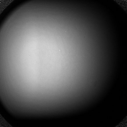
Spatial Extent
The calibration lamps in the MIS do not fully or uniformly illuminate the
entire OSMOS field. This will result in lower illumination at the ends of
the slits. There is approximately a factor of two decrease in a long slit
lamp at 5 arcminutes from the center of the field. Some points that are
farther off axis still appear completely vignetted. Complete vignetting
does not occur for the long slit, but may impact multi-slit observations.
Below is an image of the Ne lamp through the U filter that shows the
illumination pattern.

There is no comprehensive data analysis package for OSMOS; however,
Jason Eastman has written an IDL package that should be suitable for
processing imaging data. His package is described at the bottom of his
manual for
the 4k detector.
John Thorstensen has also adopted his qccds.html script for OSMOS. OSMOS-specific
documentation should be available in the near future.
The IRAF script bias4k.cl may be useful for
quick-look bias subtraction at the telescope.
Here is a collection of technical information:
- Telescope Installation and Removal Instructions
- Recommended Specifications for New Filters
- Instrument Characteristics
The slit [or disperser or a filter] wheel does not return a valid
position
Move the wheel to the nearest position with the command
- [aperture] reset
- Where aperture is slit/disp/filter1/filter2.
The connection to the IC is lost
- This may happen due to a timeout in waiting for the IC to respond. If this
does occur and an exposure is in progress, let the exposure finish. It will
still be written to the disk. To reestablish the link type:
- PR> restart
- If this is unsuccessful, try the steps outlined next in The IC stops responding
The IC stops responding
- Follow the lightning shutdown procedure (for the IC only) and restart the
software. Note in particular the following steps:
- Select 'O' on the IC computer (in the computer room) when you restart the IC
- Restart the OSMOS programs as described in the
Startup section
- If this does not work, repeat the lightning shutdown procedure
but also power off the HE on OSMOS.
- Note that the HE is the red electronics box mounted to the side of OSMOS
and its power switch is next to the digital temperature display
- Power the HE back on and continue the startup procedure described above
Instrument Status Window in Prospero does not appear
- Type startup in the Prospero window.
No connection to the guider camera
- Step 1:
- Close and reopen Maxim DL. If this does not work go to ...
- Step 2:
- Shut down the PC by holding the power button down to fully power it off,
and then start it up again. If this does not work go to ...
- Step 3:
- Close Maxim DL, go into the dome, and physically disconnect the guider
camera power supply and then reconnect it. The camera is located on the North
side of the telescope (Control Room side).
If you climb a ladder near the MIS hatch, you should see the power
cable coming out of a small box labeled FLI on the East
side. Disconnect and reconnect this cable and then go back into the
control room and restart Maxim DL.
Shutter does not open fully in cold weather
The shutter has not opened fully in very cold weather. This problem
was reported in early January 2011 and manifests as partial to
complete vignetting of the detector. The temperature at the time was
approximately -7 C and, while these conditions are rare at the site,
observers are strongly encouraged to be alert to this problem under
comparable conditions.
The connection to the IC is lost
Once the connection to the IC was lost during a call to roi4k. The
error messages were:
- Error: Requested Operation Timed Out
- ERROR: Could not get IC status
- **ERROR: Cannot get the data-taking system status
This was corrected by typing restart in the Prospero window.
One of the wheels (filter, slit, or disperser) times out
If a wheel mechanisms (filter1, filter2, slit, or disperser) returns an
error message like:
ERROR: DISPERSER DISPERSE=TIMEOUT cannot read from ...
This means the instrument electronics is not communicating with that
mechanism's controller.
The corrective action is:
- Step 1:
- Stop observing and move the telescope to the Zenith and note the camera
focus value for OSMOS if it is different than the standard value.
- Step 2:
- Shut down the OSMOS IE agent by finding the OSMOS IE console xterm window
and typing quit at the prompt.
- Alternate Way: open an xterm and type
"mdmTools stop osmos" at the Linux prompt.
- Step 3:
- Out on the telescope, power off the OSMOS IEB
(make sure it is the IE
and not the detector controller!). Count to 20, then power it back on.
- Step 4:
- Restart the OSMOS IE agent like described in the startup procedure.
- Step 5:
- Type STARTUP in the Prospero command window to restart the OSMOS session.
- Run the setup script:
call ossetup
to re-initialize the instrument, and if needed reset the camera focus to
what it was before the restart.
Principal Investigator: Paul Martini
Co-Investigator: Rick Pogge
Mechanical Engineer: Mark Derwent
Optical Engineer: Ross Zhelem
Graduate Student: Rebecca Stoll
Electrical Engineer: Dan Pappalardo
Software Engineer: Ray Gonzalez
Undergraduate Student: Man-Hong Wong
OSMOS has been generously funded by the National Science Foundation and the Center for Cosmology and AstroParticle Physics at The Ohio State University. Additional support has also been provided by the Department of Astronomy at The Ohio State University and the Department of Physics and Astronomy at Ohio University.
Return to: [
Paul's Home Page |
MDM Observatory |
OSU Astronomy Home Page
]
Updated: 2012 Dec 20 [rs/osu]
![[M51 Image]](OSMOS_M51sm.jpg)
![[OSMOS On Telescope]](OSMOS_OnTel2_Apr2010_sm.jpg)
![[QSO at z=6.4]](j1148_osmos_sm.jpg)
![[QSO at z=6.4]](osmos_mos_spectra_sm.jpg)

